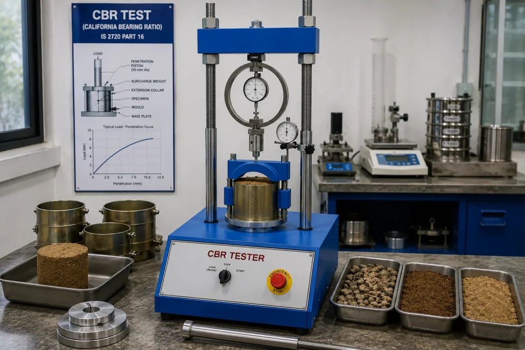
CBR Test (California Bearing Ratio): IS 2720 Part 16 Equipment & Procedure Guide
The California Bearing Ratio (CBR) test is the primary method for evaluating subgrade and sub-base strength for road and pavement design in India. Standardised under IS 2720 Part 16, this guide covers the full lab and field CBR procedure, equipment requirements, and how CBR values feed into IRC 37 flexible pavement design.
The California Bearing Ratio (CBR) test is the most widely used parameter for road subgrade and sub-base evaluation in India. Standardised under Standardised under IS 2720 Part 16:1987, the CBR value directly drives flexible pavement thickness design using IRC:37. A higher CBR means a stronger material requiring thinner pavement layers — making accurate CBR measurement critical for both economy and safety.
What is CBR and Why Does It Matter?
CBR is the ratio of the force required to penetrate a soil with a standard plunger at a standard rate, expressed as a percentage of the force required to penetrate a standard crushed stone material.
- Low CBR (2–5%) — weak subgrade (black cotton soil, silty clay); requires thick granular sub-base
- Medium CBR (5–15%) — moderate subgrade (laterite, gravel sand); typical Indian road subgrade
- High CBR (20–80%) — sub-base and base course materials (WMM, GSB); strong road-base layers
Lab CBR vs Field CBR
| Parameter | Lab CBR (IS 2720 Pt.16) | Field CBR (Dynamic Cone) |
|---|---|---|
| Specimen | Compacted in 150 mm dia mould | In-situ subgrade |
| Soaking | 4 days in water (design worst-case) | Not applicable |
| Output | CBR % at 2.5 mm and 5 mm penetration | DCP-CBR correlation per IS |
| Use | Design stage; mix design | QC during construction |
Equipment Required
CBR Testing Machine
A motorised CBR machine with:
- Load frame: 50 kN minimum capacity with motorised plunger drive
- Plunger: 50 mm diameter, cross-sectional area 19.35 cm²
- Penetration rate: 1.25 mm/min (motorised, constant rate per IS 2720 Pt.16)
- Load and penetration measurement: Digital load cell + LVDT with PC data logging
CBR Mould Assembly
- 150 mm internal diameter × 175 mm height steel mould with detachable collar (50 mm)
- Perforated base plate
- Annular surcharge weights (2.5 kg and 5 kg disc) to simulate pavement overburden
- Expansion measuring device (dial gauge on tripod) for swell measurement during soaking
Compaction Equipment
Modified Proctor rammer (4.89 kg, 450 mm drop) for compacting specimens to field density in 5 layers of 55 blows each.
Soaking Tank
Large FRP or stainless steel tank allowing full submersion with surcharge weights and dial gauge assembly for 4-day soaking.
Step-by-Step Lab CBR Procedure
- Sample preparation: Air-dry soil, break clods, pass through 20 mm sieve. Determine OMC and MDD using Modified Proctor (IS 2720 Pt.8).
- Specimen compaction: Compact in 5 layers using Modified Proctor rammer at OMC to achieve field density (typically 95–100% MDD).
- Swell measurement: Place surcharge weights on specimen. Submerge in water for 96 hours (4 days). Record swell at 0, 24, 48, 72, and 96 hours using dial gauge.
- Penetration test: Remove specimen from water. Drain for 15 minutes. Place on CBR machine. Apply surcharge. Penetrate at 1.25 mm/min. Record load at 0.5, 1.0, 1.5, 2.0, 2.5, 3.0, 4.0, 5.0, 7.5, 10.0, and 12.5 mm penetration.
- Calculation:
CBR at 2.5 mm = (Corrected load at 2.5 mm ÷ 13.44 kN) × 100
CBR at 5.0 mm = (Corrected load at 5.0 mm ÷ 20.16 kN) × 100
Report the higher value after correction.
Using CBR in Pavement Design (IRC:37-2018)
IRC:37 flexible pavement design uses design CBR of the weakest 30th percentile specimen. Enter the CBR and design traffic (in million standard axles, MSA) into the IRC:37 catalogue:
- CBR 3%, 10 MSA → Total pavement thickness ~720 mm (including subgrade improvement layer)
- CBR 7%, 10 MSA → Total pavement thickness ~530 mm
- CBR 15%, 10 MSA → Total pavement thickness ~390 mm
Every 1% improvement in subgrade CBR can reduce granular layer thickness by 20–40 mm, delivering significant material cost savings on large road projects.
Frequently Asked Questions
What is the minimum CBR for highway subgrade?
IRC:37 recommends a minimum design CBR of 5% for national and state highways. Where natural subgrade CBR is below 5%, a granular sub-base improvement layer (GSB) or lime/fly ash stabilisation is specified.
Why are 3 specimens tested per soil sample?
IS 2720 Part 16 requires testing at three compaction levels. This generates a CBR-density relationship curve from which the design CBR at field density is interpolated accurately.
What is the difference between static and dynamic CBR?
Static CBR (IS 2720 Pt.16) uses a motorised machine at 1.25 mm/min — the standard design method. Dynamic CBR uses a Dynamic Cone Penetrometer (DCP) for rapid in-situ assessment during construction, correlated to CBR using empirical equations (IRC SP 72).
View our complete Soil and Pavement Testing Equipment range including CBR machines, Proctor sets, and DCP assemblies.